Rendering
Making stuff look good
When you think about it, 3D graphics in computers seems impossible. With such limited computing power, how could we ever aim to emulate the infinite complexity of reality, 60 times per second? This area of programming, where light and magic overlap, has always seemed unreachable to me, an area of expertise reserved for the most educated and skilled programmers. The 3D-rendering course at TGA changed all that, and suddenly I felt that anything was possible.
I wanted to learn how all the popular games do it, and I wanted to do it myself. Therefore, I became responsible for all 3D-rendering in the homemade engine used by all projects that were created during the second year at TGA.


// Image Processing
Here are some image processing effects that I have implemented. None of these are taught during the Graphics Programming course at TGA. When active, these effects are applied once per frame. This requires them to be extremely fast, with the target times below a millisecond on a normal gaming computer. These effects are applied in screen space, and only need one fullscreen pass to function.
Our engine uses deferred rendering, which means that all information about the visible scene is collected before the light calculations happen. This allows for more complex image processing effects.
- Parallax Occlusion Mapping
- Screen Space Reflections
- Screen Space Ambient Occlusion
- Motion Blur
- Fast Approximate Anti-Aliasing
- LUT (Color Correction)
- Godrays
- Checkerboard Rendering
Parallax Occlusion Mapping
This technique uses a displacement (height) map to fake complex geometry on flat surfaces. The idea is that this might be used instead of having a really high-poly mesh, for example, the mesh in the gif only consists of 6 vertices.
The shader uses ray-marching for finding intersections between the rendered pixel and a blocking pixel. This intersection is found by comparing heights. Creating a ray and stepping along it is easy. The hard part about this shader was that all calculations had to be done in tangent-space. With other words, relative to the vertex-normal of the surface.
Tangent information in our pipeline is only available when generating the information about the visible scene, when looping through all meshes. This means that these calculations has to be done for every mesh that is using this technique.
Screen Space Reflections
Reflections is a hard problem to solve within real time rendering, since accurate reflections require ray-tracing, which goes against the standard rasterized model and is quite expensive. The most common solution is to use cubemaps for faking environmental lighting. Cubemaps are cheap, but provide no accurate reflections from the scene. Even with baked cubemaps, it’s nowhere close to being realistic.
But we’ve got a bunch of information about the visible scene so we might as well calculate whatever reflections we can with what we got! This effect, combined with accurate cubemaps, provides a good result while keeping the cost extremely low.
Screen Space Reflections works by taking the direction from the camera to each pixel, reflecting it against the pixel normal, and then ray marching until something is hit, breaking if something is blocking the way.
Screen Space Ambient Occlusion
Tight corners allow for less light to enter, which creates a soft shadow, often barely visible, but crucial for the realism of a scene. This shader tries to approximate this effect by comparing the normal of each pixel to a few random surrounding pixels. The larger the difference between the normals, the more occlusion.
This effect is applied before the final light calculations, and is then used in addition to the baked ambient occlusion of each model.

Motion Blur
There are two common methods for producing motion blur in video games. Per object or based on camera transformation. Both of these methods require the current and previous transform of whatever you are blurring. They are also often combined.
My implementation only applies camera based blur. The effect requires four steps:
- Calculate world position of current pixel.
- Translate world position into screen space using the transformation from previous frame. This screen space position also represents a UV coordinate.
- Calculate the UV-coordinate difference between current and previous frame.
- Sample some pixels between these coordinates and blend.
Fast Approximate Anti-Aliasing
This is an effect that you’ve probably heard of before. It is the most common anti-aliasing effect in games. This is because it is fast and easy to implement.
FXAA works in two steps. The first step tries to figure out if each pixel is an edge or not, as well as the direction of the edge. If the pixel is an edge, then the second step blends the pixels along the edge, making the edge a little blurry, but a lot smoother.

LUT (Color Correction)
LUT is a fast color correction technique which allows for a unique workflow. With some screenshots, artists change the colors however they see fit in a photo editing software, and then export their settings as a LUT-texture. When this texture is used in the LUT shader, their corrections are directly applied to the final image.
LUT stands for Look Up Table. It is the texture that makes up this table. This table has three axes where each cell has a color value. The shader uses the rgb-values of each pixel as coordinates in this table to figure how the color should be translated.
Godrays
Something I vividly remember from my Fallout 4 experience is the overwhelming godrays. Could I create something similar myself?
Godrays are rays of light visible in fog and dust. There are different ways of achieveing this effect. I settled for a simple and fast screen-space effect. A pixel is inside a ray if nothing is blocking the pixel from the light source. Step towards the light source, and add to the effect for every step that nothing is blocking! I almost couldn’t believe how easy this one was.
Checkerboard Rendering
I was playing Resident Evil when I saw an interesting graphics option called “interlaced rendering”. I discovered that this game had the ability to only render every other row of pixels each frame, almost doubling the performance with minimal graphical artifacts. The idea stuck with me, but I didn’t quite like the interlaced part of it.
I decided to try every other pixel instead. It’s easier to visualize this if you imagine the screen as a checkerboard, each pixel being either white or black. I alternate between rendering the black ones and white ones every frame. For the pixels that I don’t render, I simply reuse the pixel from the frame before.
The artifacts are most of the time very similar to a poorly implemented motion blur, and almost aren't noticable in a game with slower pace. Unfortunately, sometimes my checkerboarding-function in the shader fails and the checker-pattern becomes irregular. This might be because of rounding errors.
// Shadow Baking
Shadows are expensive. How can I make them cheaper? My goal is to avoid calculating shadows for as many objects as possible each frame.
There are two types of shadows in our engine, directional and point shadows.
Directional Shadows
The directional light in our engine does not change direction after a scene is loaded. This means that directional shadows that static objects cast can be baked. Because I want to avoid limitations for our LDs, I decided to make it possible for an infinite world size when baking. This is possible through dividing the world into a grid, baking one shadow-texture per cell.
Point Shadows
Point light shadows are a bit more complicated because of their conditions. What shadows can be baked and what can’t?
This is what I ended up with:
Static shadow + only static objects
Bake
Static shadow + dynamic objects and static objects
Bake static objects, use dynamic objects culled by camera frustum for dynamic shadows
Dynamic shadow + static objects
Use static objects culled by camera frustum
Dynamic shadow + dynamic objects
Use all objects culled by camera frustum
This means that our static point shadows needed to support a combination of baked and dynamic shadows. This was solved by simply sending two shadow cubemaps to the shader, and per pixel selecting the smallest shadow value.
This workflow wasn’t easy to figure out, but it allows every static point light in a scene to cast shadows against every static object, without affecting performance, while also allowing the closest and most important light sources to cast normal dynamic shadows.
The Baking Process
My assumption was that this baking process would be slow, and would therefore have to be saved and loaded to disk. This wasn’t the case. After this realization, I decided to bake shadows in runtime, right after the scene finished loading. But why keep the player waiting for shadows to bake? If I spread out the load over multiple frames, then the baking process almost won’t be noticeable. I decided to bake one directional shadow cell and one point shadow per frame, in order of distance to the player.


// Render Pipeline Optimizations
Producing a beautiful image is important for the overall game experience, but so is making the game feel responsive. Rendering is often the main contributor to poor game performance and responsiveness. I like fast games, poor responsiveness is among the worst thing I know in video games. Fortunately, there are increadibly many techniques for improving specifically rendering performance.
I was responsible for all 3D rendering in our engine during the second year at TGA, and if the games didn't turn out responsive, it would probably be because of my rendering pipeline. The challenge facing me gave me just the motivation I needed when researching and implementing these techniques.
Threaded Rendering
One of the most common techniques used for speeding up any kind of computer process is multithreading. My goal was to perform all rendering logic on a separate thread, thus spreading out the workload and increasing overall performance.
Buffers
Since the logic was going to communicate with the rendering a lot, I felt that there was a need for a common interface which could manage these mutex-locks automatically. Another early realization was that most communication between these parts of the engine was going to be one-sided. Almost no information had to be returned from the rendering thread.
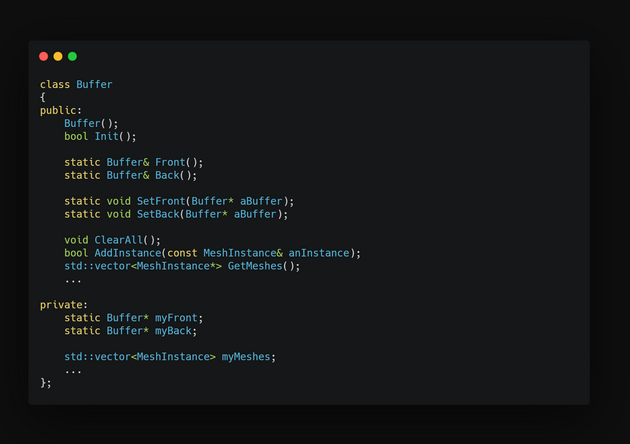
Buffer
The Buffer class was part of my solution to this problem. It manages most communication between the logic and the rendering thread. The buffer class is designed for one-time use, meaning that it is filled with information, used and then discarded.


Originally, I used two buffers in the rendering pipeline. The first one was accessed from the logic thread where it was cleared and then filled with information, while the second one was accessed from the rendering thread where the information was accessed and used. Between these buffers were a mutex that made sure the memory was safe. Once both the logic and rendering were completed, the mutex was unlocked and these buffers changed place.
Lockless Threading
If you have implemented any kind of threaded buffer system yourself, you will probably recognize this as a locked buffer system. Even though the logic and the rendering is performed in parallel, one of the threads still has to wait for the other to finish before switching these buffers. A friend to me once talked about something called lockless threading. Is this something I could use to my advantage?
Introducing a third buffer solved my problem. By having an additional "middle" buffer and using two mutex locks instead, the threading could become (almost) completely lockless! Whenever the logic thread finish an update-loop, the logic buffer and the middle buffer is switched. Whenever the rendering thread starts an update loop, if the middle buffer has been updated, the middle and the rendering buffers are switched. This means that the threads almost never have to wait for each other. There were only small differences in the rendering performance due to this change, but the logic thread which had previously spent most of its time waiting for the rendering, was suddenly running at over a thousand FPS. This also removed some stuttering caused by the previous implementation.
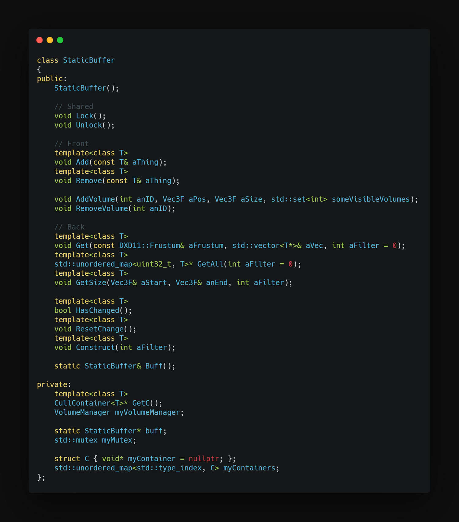
The StaticBuffer
But most objects in our scenes are marked as static. This means that their transformations do not change. It feels like a real waste to send the exact same information through a buffer every frame, just for it to be discarded.
I created a modified version of the Buffer class called StaticBuffer. There only exists one of this buffer, meaning that the mutex has to be manually locked and unlocked whenever information is accessed. This might sound troublesome because of the risk of one thread having to wait for the other, but since static objects are only added or removed when a scene loads, this isn't really a problem. In addition, to avoid having to lock and unlock this buffer thousands of times every render-loop, It is locked at the beginnig of the loop and unlocked again at the end.
Culling
is an absolute necessity in real-time 3D rendering. Culling is the process of only selecting objects which are visible. Our engine uses the camera frustum to determine if an object is visible. The frustum class is very simple. It consists of a collection of six planes, used for representing the visible scene, and a couple of functions for checking if primitive shapes are inside this frustum.
When the frustum-culling occurs is very different between static and dynamic objects. Dynamic objects are tested against the frustum before being added to the buffer on the logic thread. This minimizes the size of the buffer and avoids a lot of unneccesary copies. Static objects cannot be tested when added because of their persistent nature, and are therefore culled when retrieved from the StaticBuffer on the render thread instead.
Culling is a process which can be highly optimized, especially on static objects. First of all, it is often unnecessary to perform a cube-check against the frustum, since this requires six times more operations than a sphere check while barely improving accuracy. Besides this, it is common to do anything possible to decrease the total number of objects that has to be checked against the frustum. My original implementation divided the world into cells, where each cell is tested individually. This was a simple and effective approach, but it was in our case specific to deferred rendered static meshes and nothing else.
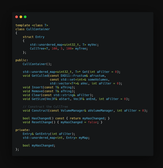
CullContainer
A common interface enables the use of templates. The CullContainer uses templates to separate between different types of cullable objects and automatically manages the data structures required by the static buffer and the culling process. This container and all the techniques mentioned below is only applied to the static buffer. I created this class to separate culling logic and object containers from the mutex logic of the static buffer. The CullContainer also provide functions for easily managing the internal containers. Check out the code snippets for an easier overview.
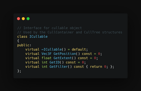
The ICullable Interface
I quickly realized that there were more things than deferred meshes that could be culled using the same methods. I decided to use a combination of templates and inheritance to automatically cull many kinds of objects. The ICullable class provides a common interface for everything required in the culling process. All an object has to do in order to be culled is to inherit from this class and overwrite its functions.
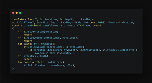
CullTree
The common interface created by the CullContainer and the ICullable culminates in this class. The CullTree is an octree specifically designed for culling ICullable objets using a frustum. The CullTree has some overhead because it has to be generated, but once the tree has been created, retrieving objects is much faster than the original cell-based approach. The CullContainer provides functionality for telling if the container has been changed since the last render-loop. If that condition is true, the CullTree is cleared and generated.
The generation process is identical to that of any octree. This Octree solves overlap by using padding, not by inserting copies of the same mesh into multiple cells. It is the retrieval process that is slightly different. When iterating over the octree, check each cell against the frustum and only step down if the cell is inside.
The CullTree is also using a grid-based approach at the top level for supporting worlds of any size. This entire process, as well as the CullTree is hidden inside the CullContainer class.


Click to enlage
Culling Volumes
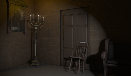
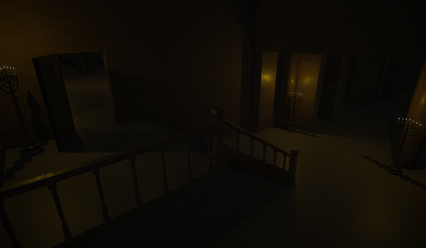
During the second project using this engine, we aimed to create a small, heavily detailed indoor world. I was able to cull objects against the camera frustum, but no checks were done against the geometry. Thousands of objects were sent to the graphics card every frame even if they were hidden behind walls.
This environment was perfect for something that I call Culling Volumes. These volumes are hand-placed by our level designers, who then specify which other volumes should be visible from the current one. When the camera is inside a volume, only the specified volumes are rendered. This puts some extra work on our LDs, but it is something that only has to be done once per room and significantly decreases the total number of objects that has to be rendered at any time. Objects outside of volumes are still rendered and culled normally, and the system supports for objects to be inside multiple volumes.
Separating the objects and culltree cells into volumes is also performed while generating the CullTree.
This is how CullingVolumes are visualized in our engine. Currently the church volume is selected, displayed in green. Neighbouring specified volumes are displayed in red.
In our engine, this culling process is used for forward meshes, deferred meshes, decals and lights.
// Skeletal Animations
Baked Skeletal Animations
TGA provided some code for skeletal animations loaded from an FBX. This code provided accurate animations, stepping through and animating the entire bone hierarchy each frame. This is an expensive way of doing it, since recursively stepping through the hierarchy requires a large number of matrix multiplications, which grow exponentially for every step down in the hierarchy. In some early benchmarks, this process took up to 20% of the frame time. All this just to produce a simple array of matrices, which are then sent to the graphics card.
My idea was that this process might be baked, storing one array of pre-calculated matrices for every frame of the animation. This meant that the most expensive part of having an animated object on screen would be to actually send those arrays to the graphics card. With other words, animations at practically no performance cost.
The baking process
This means that I need to run through the entire animation once using the original method and a fixed framerate, storing the result. With a couple of long, detailed player animations, this process actually takes quite a bit of time. Of course, we don’t want to keep the player waiting for the baking process to finish, so let's put it on another thread, letting it load in the background. Hopefully, the player won’t mind that all animations aren’t loaded the first second after starting the game.
There were two major drawbacks to this method, both relating to blending:
1. Sub-frame blending
Since the animations were baked at a fixed framerate, the playback of these animations are also at a fixed framerate. If I used a higher framerate by the baking process, it would increase memory usage and baking time drastically. This wasn’t viable.
Since the pre-calculated bone matrices are meant to be sent directly to the grapics card, they aren’t stored in a matrix-space where accurate matrix blending would work. But, at 60 fps and with minimal changes between matrices each frame, it doesn’t have to be completely accurate. Therefore I settled for a very basic matrix lerp, simply lerping between the current and next frame matrices. This worked surprisingly well, with no visible artifacts and almost no performance cost.
Baked at 15 FPS
Incorrect, notice the scaling issues
2. Animation blending
I decided to use the same method of matrix lerp as mentioned above, when blending between different animations. This time, the artifacts were visible, especially when blending between very different animations. Doing a proper transformation lerp brought no success. I believe that there is no way of solving this without making big changes to the way that the matrices are stored. This is a problem I have yet to solve.
Bone Socketing
is the process of attaching in-game objects to the bones of an animation. It is a simple but very useful tool. In principle, all you have to do is to transform the final bone transformation into local-space compared to the parent object. Our implementation was simple, just put an entity as a child to an animated object, and give the entity the same name as the bone you want it to follow. The offset between original transformation of the entity and the bone is stored and applied each frame, allowing for precise positioning.
Additive Animations
is the process of combining animations by adding the result of their bone transformations. In order to play multiple animations at the same time using the same animator, I had to add support for animation layers. Each layer has it's own state-machine with custom transitions and states, while properties are shared across all layers.
This is a case where baking the animations actually made everything a lot easier. Because the transformations already were relative to their origin, all I had to do was to multiply each layer in the correct order. Sometimes an additive animation should only be applied to some bones. This was solved by specifying a root bone in the animation layer. Only bones below the root in the hierarchy are affected by that layer.
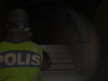
The main character in the police game uses a combination of all of these features. Bone socketing is used to attach the flashlight to the hand and additive animations are used to keep his hand up while the flashlight is lit.
Baked at 1 FPS
Correct, similar animations
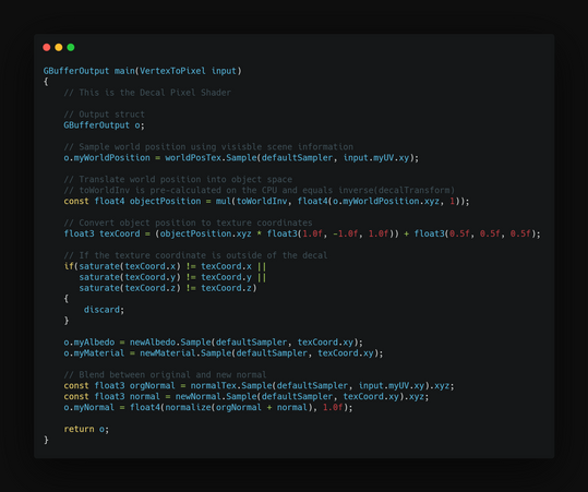
// Decals

Decals are textures that are projected onto other models. It's perfect for effects like dust, dirt and blood. Our decals follow the same pipline as deferred rendered objects. They are culled and statically optimized the same way, the main difference being that they use cubes for projection instead of uv-mapped models.
Decals do not affect the depth buffer and only overwrite existing information about the visible scene. This means that our decals use exactly the same lighting calculations as normal meshes, while not affecting the performance of these calculations at all.
Projections
This is an area of computer graphics that has always been a little extra magical to me. The calculations that this effect required was something that I had a hard time visualizing before actually sitting down and spending time thinking about. Reading about decals online was a good starting point, and got me thinking about our home cinema. How does that image project onto our wall? What was the uv-translation that I was trying to achieve?
Translations
The solution came to me in reverse order. The final UV is in the object space relative to the projection cube. Since the cube is uv-mapped 0-1 on each face, a position in object space would (almost) directly represent the UV. All I need to figure out is how to translate the screen position to local object space.
That translation happens in two steps:
- Figure out world position of the underlying pixel. I did this by sampling the visible scene information generated by the deferred pipeline.
- Translate world position into the object space of the projection cube. To do this, I had to multiply the world position with the inverse of the world matrix for the projection cube.